
Ground Control for Railway Drone Surveys — 2,000+ km
Railways · Singrauli–Katni–Jabalpur and other corridors, India
Project Overview
Across a series of UAV mapping projects on Indian Railways corridors, BTPL supplied the ground control the aerial survey is constrained to — more than 2,000 km of corridor control in aggregate, including about 330 km on the Singrauli–Katni–Jabalpur route. The work was commissioned for Indian Railways through Matrix Geo Solutions Ltd. BTPL's scope was the control itself: reconnaissance, marking, observation, adjustment and documentation of the coordinated framework. Aerial capture and photogrammetric production fell outside that scope.
What did the client require?
A photogrammetric corridor survey is only as good as the ground control it is constrained to. The aerial block carries no absolute position or scale of its own, and along a corridor it is geometrically weak in the very direction the alignment runs, so coordinated marks distributed through the length of the route are what hold the model to the ground and stop it bending or drifting between blocks. On railway work the framework has a second job: it must sit on the datum and vertical reference the railway's design is worked in, so that heights derived from the model can be read against the existing formation. Independent check points and a documented accuracy statement exist for the same reason — the quality of mapping produced on the framework has to be demonstrable from independently observed points.
What made this project challenging?
- More than 2,000 km of corridor in aggregate, spread over several separate projects, each network observed and adjusted on its own while the specification, marking convention and reporting stayed identical from one project to the next.
- The geometric weakness of a long, narrow control network: with almost no width to brace it, a corridor framework depends on station spacing, redundant baselines and firm ties to published reference to stop error accumulating from one end of the route to the other.
- Where cuttings, embankment slopes, tree lines or lineside structures take away the sky, GNSS reception degrades and multipath appears, so a convenient mark position had to be given up or its occupation extended.
- Marks had to stay in place and stay visible from marking until aerial capture, an interval falling outside BTPL's scope; and their size, form and distribution had to suit the flight lines and mapping scale of the survey the control was being supplied for, so the point plan had to be settled before marking began.
How did BTPL carry out the survey?
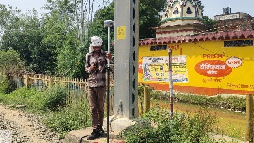
Each corridor opened with reconnaissance along the route to fix mark positions that were stable, safely reachable, clear of the running line, open to the sky and — the constraint that governs photogrammetric control — visible from above, on ground unlikely to be disturbed before the flight. Marks were then constructed and targeted so that the centre could be identified in the imagery. Observation followed in differential mode, base and rover, with static sessions on the framework stations; occupation length was set case by case, against baseline length and against how much sky the cutting, tree line or structure had taken away. Redundant baselines were carried through the chain so that the network could be adjusted and tested, and a proportion of the points was held back from the control set released for the aerial adjustment and reserved as independent check points. The same procedure was repeated corridor by corridor across the projects, so that the framework had the same character on every one.
How was the data processed?
Each corridor was adjusted as a network in its own right. Baselines were computed from the recorded sessions and taken into a least-squares adjustment, with residuals examined station by station before any coordinate was accepted; where residuals would not settle, the station went back for re-observation. Accepted positions were then transformed onto the datum, projection and vertical reference agreed for the project, so that what BTPL released needed no further conversion before use. Compilation came last: coordinates, heights, mark type and station descriptions with sketches and access notes were drawn together into the corridor register and issued with the adjustment output and the accuracy report.
How was accuracy verified?
Closed figures and repeated baselines were observed through each network so that the adjustment itself had something to test. Stations were re-occupied in separate sessions under different satellite geometry and the two solutions compared. The base positions used on a corridor were verified again during the work, so that a shift at the reference could not travel out along the route unnoticed. Marks were recovered from the written description alone as a check that the description worked, and a description that did not lead to the mark was rewritten. Points held out of the released control set were issued separately as independent check points for testing the aerial solution. Adjustment residuals, transformation parameters and the register itself were reviewed against the project specification before the accuracy report was signed off.
What was delivered?
Each corridor was closed out with an adjusted and documented framework — coordinates, station descriptions, check points and an accuracy report — and in aggregate the projects account for more than 2,000 km of Indian Railways route, including about 330 km on Singrauli–Katni–Jabalpur. Because every corridor was held on one datum from end to end and observed to a common specification, mapping constrained to that framework can be tied consistently along the full route, and its quality demonstrated against independently observed check points issued for that purpose.
Indian Railways, through Matrix Geo Solutions Ltd.
Deliverable extracts (orthomosaic, terrain, CAD) will be added once cleared for publication (client-sensitive information removed per BTPL policy).
Planning a Similar Project?
Share your location, scope and required deliverables — BTPL will propose the appropriate survey methodology.