
NCRTC Corridor Survey — Sarai Kale Khan, Delhi to Sonipat Border
Railways & Metro · Delhi to Sonipat border, Haryana
Published · Updated
Project Overview
Bearing Technology Private Limited (BTPL) carried out a corridor survey of approximately 30 km of new rail alignment from Sarai Kale Khan in Delhi to the Sonipat border in Haryana, for NCRTC through Mega Engineers, Noida, delivering a continuous, chainage-referenced record of the corridor on one datum.
BTPL carried out the topographic corridor survey for a new rail alignment for NCRTC, through Mega Engineers, Noida, extending approximately 30 km from Sarai Kale Khan in Delhi to the Sonipat border in Haryana. The survey covered the corridor width required for alignment studies, capturing ground levels, existing structures, crossings, utilities and boundary detail on a single continuous control framework. The output was prepared as a chainage-referenced dataset suitable for direct use in alignment design.
What did the client require?
The corridor survey was required to provide a continuous and dimensionally reliable base along the proposed route, so that horizontal and vertical alignment could be developed and every interface with existing infrastructure identified. The data was also needed to inform assessment of the land extent involved and to bring out conflicts with existing roads, rail lines, drains and utility corridors. Because the corridor spans two jurisdictions, all data had to sit on one consistent horizontal and vertical datum from end to end.
What made this project challenging?
- Maintaining a single consistent horizontal and vertical framework across 30 km of corridor crossing the administrative boundary between Delhi and Haryana
- Built-up urban stretches with restricted and permission-dependent access to private land, occupied plots and secured premises
- Survey work alongside live traffic on busy carriageways and at road crossings, requiring short working windows, traffic-aware setups and safety cover for field crews
- GNSS multipath and signal obstruction near flyovers, high-rise development, overhead power lines and existing rail and metro structures, requiring conventional traversing to bridge affected sections
- Crossings of drains, canals, service corridors and existing rail infrastructure, each needing detailed capture of levels, clearances and structural extents
How did BTPL carry out the survey?
A primary GNSS control chain was established along the length of the corridor at regular intervals and connected by precise levelling so that every survey party worked to the same horizontal and vertical framework. Control was densified by closed traverses through built-up and obstructed stretches where satellite observation was unreliable, giving continuous coverage without breaking the datum. Detail survey was then executed by total station and RTK, with the corridor divided into manageable reaches and adjacent reaches deliberately overlapped so that the work of separate crews could be compared. Constrained locations — carriageway crossings, live rail interfaces and congested junctions — were surveyed in agreed working windows with the necessary permissions in place, and all reaches were finally merged into one chainage-referenced corridor model.
How was the data processed?
GNSS baselines and traverse observations were processed and adjusted as a single network before detail data was accepted, with the level network adjusted independently and carried through the full corridor. Coded field data was assembled into continuous strings and surfaces, from which the strip plan, Digital Terrain Model, longitudinal section and cross-sections were generated against the agreed chainage. Structures, utilities and crossings were compiled as separate identified layers so that design interfaces can be isolated from general topography.
How was accuracy verified?
Traverses and level runs were closed onto independent control, and levelling was double-run so that misclosure could be assessed against accepted survey practice before acceptance. Detail was verified by observing independent check points from separate setups, and overlapping reaches surveyed by different crews were compared to confirm agreement along the corridor. Feature coding and structure attributes were checked in the field against the compiled plan, and cross-sections were reviewed against observed ground levels before issue.
What was delivered?
The survey was delivered through Mega Engineers, Noida for NCRTC as a continuous, chainage-referenced record of the 30 km corridor held on one consistent datum, allowing horizontal and vertical alignment to be developed without gaps or datum breaks between reaches. The structure, utility and crossing inventory gives the design and land teams a clear view of the existing interfaces along the route, supporting land requirement assessment and early resolution of conflicts.
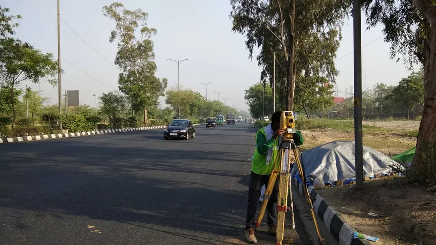
NCRTC, through Mega Engineers, Noida
Deliverable extracts (orthomosaic, terrain, CAD) will be added once cleared for publication (client-sensitive information removed per BTPL policy).
Planning a Similar Project?
Share your location, scope and required deliverables — BTPL will propose the appropriate survey methodology.