
Hydro-Electric Projects — 3 Sites, J&K
Power & Hydro · Jammu & Kashmir
Project Overview
BTPL carried out UAV photogrammetric topographic surveys at three hydro-electric project sites in Jammu & Kashmir, engaged by NHPC as a third party. Each site was surveyed on its own control framework and delivered as a self-contained coordinated dataset — orthomosaic, terrain model, contours and CAD drawings — with the three held on a common datum so that they could be read together.
What did NHPC require?
A hydro-electric project spreads its components across a valley: diversion or barrage works, intake, waterway, surge arrangement, powerhouse, tailrace, adits, muck disposal areas, and the approach roads and construction platforms that serve them. Every one of those has to be placed on ground whose shape is known, because a small difference in level can decide whether a platform is buildable, how much excavation it needs, and where an access road can run. A terrain model is therefore the base for layout, for earthwork and quantity assessment, for judging the slopes above and below each component, and for defining the extent of land involved.
What made this project challenging?
- Three sites, three mobilisations and three independent control frameworks, with the drawing set at each having to match the other two in datum, content and standard.
- Relief within a single survey block, which puts control on more than one level: the network had to span the height range of the block and not only its plan extent, and flight lines had to follow the ground surface.
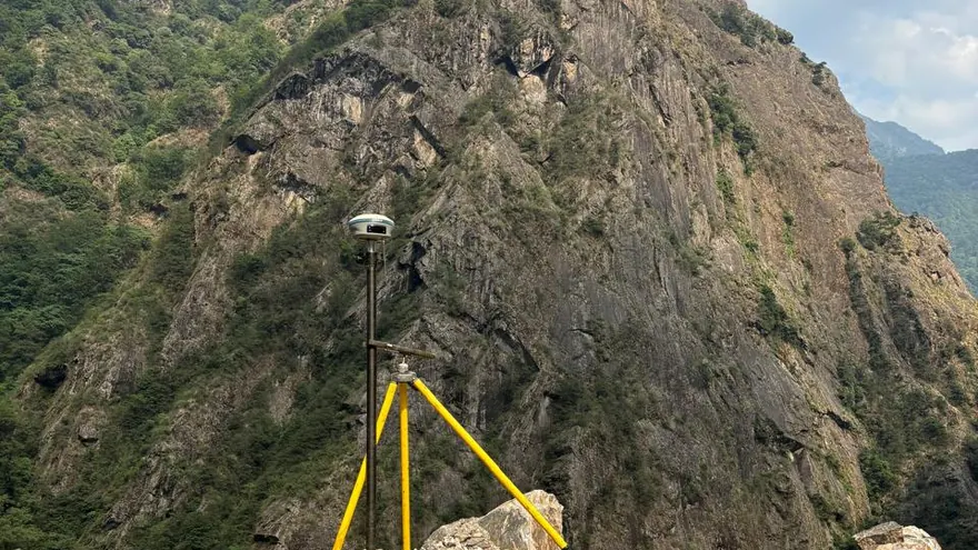
- Ground on which the placing and observation of ground control is limited to where a crew can safely stand — and that limit sets the geometry available to the photogrammetric solution.
- Satellite visibility and radio link that cannot be assumed everywhere on a site, so sessions and occupations were planned around obstruction where it occurs.
- Shadow and vegetation cover, where they fall across a block, both of which weaken image matching and make the bare ground harder to recover.
How did BTPL carry out the survey?
Each site was treated as a discrete survey with its own control framework, observed by GNSS, tied to the national datum and connected to available project reference marks so that the survey agreed with the levels already in use at the site. Ground control and independent check points were pre-marked and observed on that framework, positioned so that the network spanned the height range of the block and not only the accessible ground at the valley floor, which is what keeps the vertical solution honest where relief is large. Capture was then planned site by site, with terrain-following flight lines, planned forward and side overlap, cross strips at the block ends, and oblique passes where a nadir-only flight represents the ground poorly. Where slope, shadow, vegetation or water stopped the aerial data resolving the ground reliably, supplementary ground observation was taken on the same framework and carried into the model.
How was the data processed?
Three blocks were processed to one specification. Each was triangulated on its own ground control, matched to a dense cloud, and classified for bare ground, with the classification taken back to manual review wherever shadow or vegetation made the automatic result unreliable. Terrain model and orthomosaic followed from the accepted classification at each site. Contour generation needed the most editing: where the ground falls away quickly the drawn interval crowds, so lines were thinned and then checked against the model to keep the drawing readable without letting it depart from the surface it came from. Planimetric detail was taken into CAD from the orthomosaic and the field records, and the three drawing sets were compiled on one datum and projection.
How was accuracy verified?
Check points were withheld from the adjustment at the top of each block as well as on the valley floor, so that the tested part of the model took in ground no crew could walk over. Overlap between adjacent strips and blocks was compared for continuity of the merged surface. Classified ground was reviewed against the imagery on shadowed and vegetated slopes, and modelled levels were compared with ground-observed spot levels where those were taken. Contours were checked back against the terrain model, with attention to the places where the interval is doing the most work. The last check at each site was whether its drawing set opened alongside the other two and read as one datum, which is the whole point of surveying three separate valleys to a single specification.
What was delivered?
Layout, platform and access planning, earthwork assessment and slope appraisal at the three sites can be taken forward on measured terrain. Each site was issued as its own coordinated dataset — orthomosaic, terrain model, contours and CAD drawings — with the three held on a common datum, and each produced by BTPL in a third-party capacity.
NHPC (as third party)
Deliverable extracts (orthomosaic, terrain, CAD) will be added once cleared for publication (client-sensitive information removed per BTPL policy).
Planning a Similar Project?
Share your location, scope and required deliverables — BTPL will propose the appropriate survey methodology.