
Ernakulam Greenfield Bypass Road
Roads & Highways · Ernakulam, Kerala
Project Overview
BTPL carried out the UAV photogrammetric corridor survey for a 45 km greenfield bypass alignment at Ernakulam, Kerala, engaged by Balaji Surveyors Pvt Ltd with NHAI as the end client. On a route with no road on it there is nothing on the ground to hang a survey on — no formation, no kerb line, no chainage — so the framework, the chainage and the terrain model all had to be created before any design question could be put to the data. Coverage was taken as a strip through the length of the proposed route, wide enough to carry the alignment wherever the design might place it.
What did the client require?
A bypass exists to take through traffic off a road that can no longer carry it, and the route it takes has to be fixed across land already in other use. That decision cannot be made on a centre line: the design office needs a strip wide enough to test alternatives against each other on identical data, to set the vertical profile, to compute earthwork, and to site the structures where the alignment meets watercourses and existing roads. The same dataset carries the land question — which holdings, buildings, plantation, cultivation and water bodies fall inside the proposed width — and on a corridor of this kind that question can constrain the alignment as much as the terrain does.
What made this project challenging?
- No existing road or formation to work from: control, chainage and terrain model all had to be created before there was anything for the design to measure along.
- Where plantation and tree canopy close over the ground, they hide the bare surface from the camera and obstruct the sky at exactly the positions a control mark would otherwise want.
- Holding one datum and one continuous chainage across the full 45 km, so that alternatives studied at different points along the route are compared on the same framework.
How did BTPL carry out the survey?
Because there was no route on the ground, the first decision was about reference. The whole 45 km was put on one framework before any of it was surveyed: GNSS observed along the full length and tied to published reference, carrying a single horizontal and vertical datum end to end, and a continuous chainage established along the proposed route so that separately surveyed blocks would still compare. Ground control and check points were then marked into that framework, sited where the sky was open and where the mark would stay undisturbed and stay visible from above — under canopy that is a real constraint on where a point can go — and observed by DGPS and RTK. Aerial capture followed in successive blocks with planned forward and side overlap and deliberate tie-in between them. Ground survey on the same framework then took what imagery could not: true ground level beneath plantation and tree cover, detail in enclosed and built-up pockets, and bank and bed information at the watercourse crossings. Aerial and ground data were merged into one corridor model before any drawing was produced.
How was the data processed?
Aerial triangulation was constrained to the surveyed ground control and dense image matching produced the corridor point cloud, which was classified into ground and everything standing on it — canopy, buildings, walls. Under closed canopy the density of genuine ground returns is what limits the terrain model, so those stretches were edited against the RTK levels observed there before the surface was accepted, and the DTM and orthomosaic were produced from it. Extraction then differed from work on an existing road in one respect: with no formation to follow, the longitudinal profile had to be cut along the proposed route on the chainage established for the survey, with contours and planimetric detail referenced to the same line. Land use, buildings, plantation, water bodies and crossings were compiled as identified layers, and plan and profile assembled into alignment sheets.
How was accuracy verified?
Independent check points held out of the adjustment were used to verify the model along the corridor. Under plantation and tree cover, RTK levels were observed specifically for comparison against the classified surface, and the classification was corrected where the two disagreed. Overlap between adjacent blocks was compared to confirm the merged corridor ran through without a step. Contours were reviewed against observed spot levels, and the ground-surveyed detail at crossings and in enclosed pockets was checked for agreement with the aerial data where both cover the same ground. Chainage referencing, feature layering and sheet presentation were verified against the agreed drawing standard before issue.
What was delivered?
Alignment options can be compared against each other, the vertical profile fixed, earthwork and structures assessed, and the holdings, buildings and cultivated land falling within the corridor identified — all from one dataset. It was delivered to Balaji Surveyors Pvt Ltd, for NHAI, as a single coordinated base for the full 45 km: orthomosaic, terrain model, contours and alignment sheets on one datum and one continuous chainage, produced entirely from new survey.
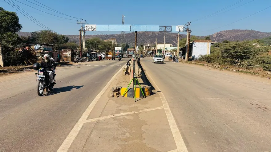
NHAI · via  Balaji Surveyors Pvt Ltd
Deliverable extracts (orthomosaic, terrain, CAD) will be added once cleared for publication (client-sensitive information removed per BTPL policy).
Planning a Similar Project?
Share your location, scope and required deliverables — BTPL will propose the appropriate survey methodology.