
Dimapur Railway Doubling Project
Railways · Dimapur, Nagaland
Project Overview
BTPL was engaged by Iris Aerial Innovations Pvt Ltd to survey a 45 km railway doubling corridor at Dimapur, Nagaland, by UAV photogrammetry on a GNSS control framework carried the full length of the route. A doubling scheme fits a second line to a line that already exists, so the survey had to describe the corridor as it stands: the existing formation together with the strip of ground on either side within which the second line, its drainage and its structures would fall. The output was issued as alignment sheets and terrain data referenced to route chainage.
What did Iris Aerial Innovations Pvt Ltd require?
A second line has to be fitted to ground that is already committed — to an existing formation, to the railway's land boundary, and to the crossings, culverts and drainage that serve the line already there. The design therefore needs the existing formation and the adjoining ground held on one surface and one datum, so that the new grade can be set in a defensible relationship to the existing line and the earthwork between them computed from measured ground. It also needs the corridor's features located, because each crossing, waterway opening, structure and boundary line is a point at which the doubling proposal has to be resolved. Alignment sheets referenced to route chainage are the form in which that information reaches the design office usable.
What made this project challenging?
- Where vegetation and tree growth stand along and beside the formation, the bare ground, the embankment toe and the drainage line are hidden from the camera, which makes ground classification, not capture, the governing task.
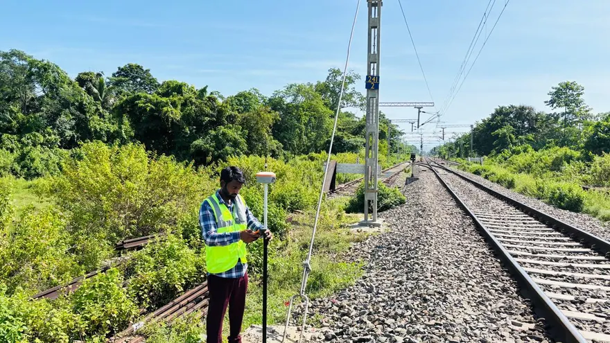
- Work near the running line depended on clearances, and every mark and every ground observation within reach of the track had to be placed and occupied within the railway's safety requirements.
- Where structures and roadside occupation stand close to the railway boundary, detail had to be taken up to the land limit, subject to access permission.
- Carrying one horizontal and vertical framework the full 45 km and tying it to the railway's own reference marks where the route offered them, so that derived levels could be read against the existing track and formation.
How did BTPL carry out the survey?
The framework went in first and was carried the length of the 45 km strip, hung off the railway's own reference marks where the route offered them so that a derived level could be read straight against the existing formation. What that framework then had to support was decided by what the camera would not deliver: under closed canopy there are few genuine ground returns, at a culvert there is no way to see an invert from above, and behind roadside building the ground is enclosed. Supplementary ground survey was therefore planned onto the same framework from the outset, to take bare ground beneath tree cover, track features, culvert and bridge openings and invert detail, level crossing geometry, and the pockets the aerial view could not reach. Control and check points were marked on ground that would stay undisturbed and stay visible from above, then observed by DGPS and RTK. Flying followed in corridor blocks with planned forward and side overlap and deliberate tie-in at the joins, taken when clearances near the running line permitted. The ground observations were carried into the model itself, so that the corridor compiled as a single body of data.
How was the data processed?
Aerial triangulation was run against the surveyed ground control and dense image matching built the corridor point cloud. The work that governed the outcome came next: separating ground from vegetation, track structures and building, which along the vegetated reaches had to be edited by hand because the genuine ground returns there are thin, and checked against the RTK levels observed in those same reaches. The DTM and orthomosaic came off the edited surface. Extraction into CAD was then organised against route chainage — contours, the longitudinal profile and the planimetric detail from the model, with the ground-surveyed track, crossing and structure detail merged into the same drawing set. The sheets were assembled so that plan and profile for each reach of the corridor read together.
How was accuracy verified?
Where the framework had been tied to railway benchmarks or track-level reference points, heights were checked back against them. Where canopy closed over the ground, RTK levels were run through and set against the modelled terrain; where the surface sat high, the cause was traced back into the classification and the classification corrected. Check points held out of the aerial adjustment gave the general test of the model along the rest of the corridor. Block joins were examined in their overlap so that no step survived into the merged strip. Ground-surveyed culvert, bridge and crossing detail was compared against the aerial model wherever the two describe the same feature. Chainage referencing, sheet continuity and contour behaviour against observed spot levels were the last checks before the alignment sheets went out.
What was delivered?
The corridor was handed over as one continuous, chainage-referenced record of all 45 km, with the existing formation and the adjoining ground on a single surface and a single datum — orthomosaic, terrain model, contours and alignment sheets. From that base the doubling alignment, its earthwork, its drainage and its interfaces with the existing crossings and structures can be developed together, and the extent of land involved along the route read off the same data.
Iris Aerial Innovations Pvt Ltd
Deliverable extracts (orthomosaic, terrain, CAD) will be added once cleared for publication (client-sensitive information removed per BTPL policy).
Planning a Similar Project?
Share your location, scope and required deliverables — BTPL will propose the appropriate survey methodology.