
Delhi Zoological Park — Topographic & GPR Survey
Urban / Government · New Delhi
Published · Updated
Project Overview
Bearing Technology Private Limited (BTPL) carried out a topographic survey of approximately 350 acres of the Delhi Zoological Park together with a Ground Penetrating Radar survey, for CPWD, delivering one coordinated base plan of above-ground topography and interpreted subsurface services.
BTPL was engaged by CPWD to carry out a topographic survey of the Delhi Zoological Park covering approximately 350 acres, together with a Ground Penetrating Radar survey within the same campus. The assignment combined an above-ground detail and level survey with a non-destructive subsurface investigation, executed on a single common control framework. Both datasets were referenced to the same coordinate system and datum so that surface features and detected subsurface indications could be read together on one base plan.
What did CPWD require?
CPWD required a current, dimensionally reliable base plan of the campus to support planning and design work, including circulation, drainage and services review. The GPR component was required to indicate buried services and subsurface anomalies ahead of design and excavation, since service records for a campus of this age and extent are typically incomplete. The combined output had to be directly usable by architects, service consultants and execution agencies working on one coordinated base.
What made this project challenging?
- A live public facility with animal enclosures, restricted zones and visitor movement, requiring survey work to be sequenced around operational timings and site access permissions
- Tree canopy over parts of the campus degrading GNSS reception, requiring conventional traversing to reach obscured detail
- Enclosures, moats, boundary walls and water bodies breaking line of sight and preventing continuous instrument setups across the site
- Varied ground surfaces across the campus — paved paths, compacted tracks, lawns and soft ground — affecting GPR coupling and penetration, requiring acquisition settings to be reviewed line by line
- No reliable as-built record of existing buried services, so subsurface interpretation had to be corroborated against visible surface evidence such as chambers, valve covers and inspection pits
How did BTPL carry out the survey?
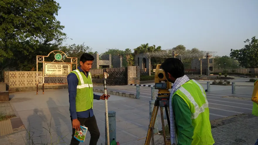
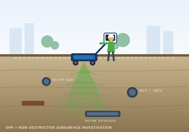
Work began with the establishment of a primary control network across the campus using GNSS observations, densified with traverse stations and connected by levelling so that every part of the survey area was captured on one consistent horizontal and vertical framework. Topographic detail, spot levels, structures, paths, drainage features, water bodies and tree positions were then captured by total station and RTK, with feature coding applied in the field. GPR acquisition was carried out on a planned grid of lines along paths, open ground and areas of proposed intervention, with each line set out and recorded against the same survey control. Surface survey and GPR interpretation were subsequently merged into a single georeferenced base plan so that detected subsurface indications sit correctly against above-ground features.
How was the data processed?
Control observations were reduced and adjusted before any detail data was accepted, after which the coded field data was drawn up into a CAD base plan with contours generated from an edited terrain model. GPR records were processed through standard gain, filtering and background removal steps, with depth conversion based on velocity calibration derived from hyperbola fitting on site records. Interpreted linear features and anomalies were picked line by line, correlated across crossing lines and digitised onto the topographic plan as a separate, clearly identified layer.
How was accuracy verified?
The control network was checked by closed traverses and closed level loops, with misclosure assessed against accepted survey practice before acceptance. Detail capture was verified against independent check points observed from separate setups. Terrain modelling was reviewed for breakline integrity and for consistency between contours and observed spot levels before contours were issued. GPR interpretations were cross-validated at line intersections and, where possible, corroborated against visible surface evidence of services, with the assumptions and limits of the interpretation recorded in the deliverable.
What was delivered?
CPWD received a single coordinated base plan of the campus in which above-ground topography and interpreted subsurface information are held on one control framework and can be read together. The GPR layer allows excavation and new service routing to be planned with an informed view of likely buried services. Interpretation is indicative, and is issued on the basis that indicated features are confirmed by trial pit or safe exposure before excavation.
 CPWD
CPWD
Deliverable extracts (orthomosaic, terrain, CAD) will be added once cleared for publication (client-sensitive information removed per BTPL policy).
Planning a Similar Project?
Share your location, scope and required deliverables — BTPL will propose the appropriate survey methodology.