
Interstate Bus Terminals — Topographic Surveys
Urban Development · Delhi
Project Overview
DTIDC engaged BTPL to carry out topographic surveys at interstate bus terminals in Delhi. Each terminal was surveyed on control established at that site, recording buildings, platforms and bays, paved circulation areas, drainage and the site boundary. Deliverables were prepared terminal by terminal as topographic plans and site plans in CAD, all to a common specification.
What did DTIDC require?
Remodelling, resurfacing, extending or redeveloping a bus terminal depends on knowing what stands on the site and at what level. Bus manoeuvring, boarding and parking are governed by the geometry and gradients of the paved surface, so levels across aprons and platforms matter as much as plan dimensions. Drainage of paved areas has to be designed against measured falls and the recorded position of existing gullies and chambers. The surveyed boundary, entries and exits define the extent available to work within.
What made this project challenging?
- Paved aprons and circulation areas across each terminal, which had to be covered by dense level capture rather than by a sparse grid of points.
- Terminal buildings, canopies, platform structures breaking line of sight and obstructing GNSS reception, requiring closed traverse through the site to reach every setup position.
- Built detail at close quarters — platform edges, kerbs, columns, ticketing and service structures, boundary walls, entries and exits — needing feature-by-feature capture in confined space.
- Drainage features that could not all be reached or opened, so accessible chambers were recorded and the remainder noted as unverified.
- Multiple separate terminals, each with its own access arrangements, to be surveyed to one specification and delivered as a consistent set.
How did BTPL carry out the survey?
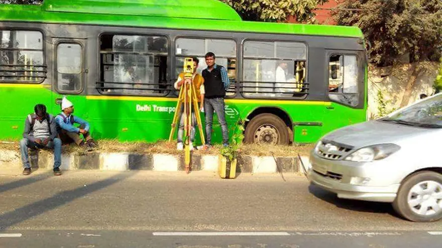
At each terminal, BTPL first established GNSS control at points chosen for sky visibility and for their usefulness in serving the site, then densified it by closed traverse through the covered and obstructed parts of the terminal where satellite observation is unreliable. Heights were carried across the site through that same control, so that apron, platform and building levels all sit on one datum. Detail was captured principally by total station, with RTK used only in the open areas where reception allowed: platform edges and kerbs, canopy and building lines, columns, boundary walls, entries and exits, parking and bay markings, signage and service structures, together with dense spot levels across the aprons and along every break in the paved surface. Gullies and chambers were recorded where they could be safely reached, with invert levels taken where a chamber could be opened. Fieldwork was sequenced around whichever part of a site was available, with the separate reaches tied together through the site control.
How was the data processed?
Each terminal yielded two drawings from one survey. Control and traverse observations were adjusted and levels reduced before anything was drafted; the coded detail then went into the topographic plan, with breaklines carried along kerbs, platform edges, channels and every change of surface so that modelled levels follow the paved geometry instead of smoothing across it. The site plan was drawn from the same data, with structures, circulation, bays, parking and boundary held as identified layers so that the two drawings can be read separately or one over the other. Drainage was compiled onto a layer of its own, with observed invert levels annotated where a chamber could be opened and the remainder marked unverified.
How was accuracy verified?
Every traverse through a terminal was brought back onto independent control and its misclosure judged against accepted survey practice before any of the detail was drafted. Apron and platform levels were re-observed from separate setups and the two sets compared. Detail was checked against points observed from different stations. The plotted plan was then walked against the site, confirming structures, bays, circulation and the drainage features shown. Each terminal's drawing set was finally checked against the same layering and content specification, so that the set is consistent from site to site.
What was delivered?
Each terminal is now recorded as a CAD topographic plan and a site plan, showing buildings, platforms, paved areas, circulation, drainage and boundary as measured on one site datum. The level data supports resurfacing, regrading and drainage assessment across the paved areas, and the site plans give a measured base for remodelling, capacity and circulation studies. Because every terminal was surveyed to one specification, the sites can be reviewed and planned as a group.
DTIDC
Deliverable extracts (orthomosaic, terrain, CAD) will be added once cleared for publication (client-sensitive information removed per BTPL policy).
Planning a Similar Project?
Share your location, scope and required deliverables — BTPL will propose the appropriate survey methodology.