
GPR Subsurface Survey — DDA Area
Urban Development · Delhi
Project Overview
BTPL carried out a Ground Penetrating Radar survey for the Delhi Development Authority in Delhi, to indicate what lies beneath the surface without excavation. Radar lines were run on a planned grid across the investigation area, with each line set out and recorded against GNSS-observed survey control so that anything detected could be plotted in its true position. The work was delivered as a subsurface feature map and a georeferenced CAD overlay on the site base, supported by a report setting out the basis and the limits of the interpretation.
What did DDA require?
Excavation on developed land can meet buried services and structures that are not shown on any drawing available to the work, and the consequences of finding a service with a machine range from damage and delay to real danger where power or gas is involved. Ground Penetrating Radar addresses this without digging: a pulse transmitted into the ground reflects wherever the electrical properties change — at a pipe, duct, cable, slab, void or old foundation — and the returns, recorded continuously along a line, build a section through the ground. Positioning those sections on survey control is what turns a set of reflections into a usable plan of where buried features are to be expected, so that layout, service routing and excavation can be planned before the ground is opened.
What made this project challenging?
- No service record was available to the survey, so the grid had to be planned to search the ground systematically rather than to confirm known runs.
- Surface and ground conditions that govern antenna coupling and the depth the radar reaches, so acquisition settings were reviewed against the response actually being returned rather than fixed at the outset.
- Conductive ground, where present, attenuates the signal and limits penetration however the survey is configured — a physical limit to be reported rather than designed around.
- Where services run close together, overlapping reflections that are difficult to resolve into individual features.
- Reflections that resemble services but arise from other buried material, separable only by pattern, by continuity across adjacent lines and by corroborating surface evidence.
- Surface obstructions, which interrupt line runs and force lines to be broken and restarted while the positional record is kept continuous.
How did BTPL carry out the survey?
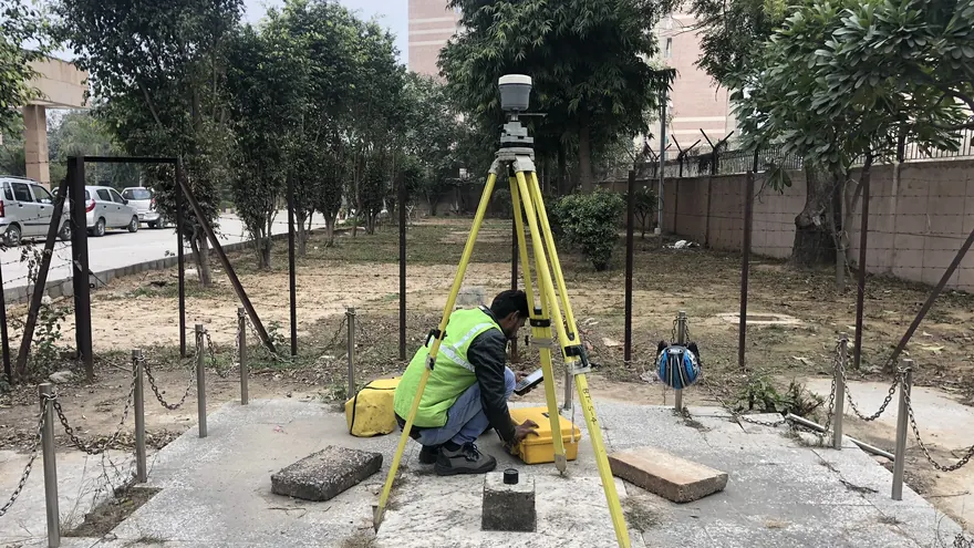
The investigation area was first brought onto GNSS survey control so that every acquisition line could be set out, recorded and later reproduced in position. Radar lines were laid out as a grid at a spacing chosen to give a reasonable prospect of intersecting linear features, with cross lines run so that a feature would be crossed more than once and could be traced rather than inferred from a single reflection. Acquisition parameters were set on site and revisited as surface and ground conditions changed across the area. Visible surface evidence of buried services was recorded during acquisition where present, since an anomaly that lines up with visible surface evidence can be interpreted with far greater confidence than one that stands alone. Where an obstruction interrupted a line, it was broken and restarted against control so that the recorded position of the data remained continuous through the gap.
How was the data processed?
Radargrams were corrected for time zero and then gained, filtered and background-removed, with settings chosen to bring genuine reflections out of the record without manufacturing features the data does not contain. Radar velocity was derived by fitting the hyperbolic returns that point targets leave in the records, and used to convert reflection travel time into indicative depth. Picking was done line by line, and a pick was carried forward as a linear service only if it could be followed onto crossing and adjacent lines; single-line returns were held as anomalies. The features that survived that test were georeferenced through the recorded line positions and digitised onto the site base as a distinct overlay layer, kept clearly separate from surveyed surface detail.
How was accuracy verified?
Coverage was reviewed line by line against the planned grid, so that any gap left by an obstruction was identified and stated instead of being closed by interpolation, and stretches where penetration was restricted were recorded as such. Velocity was calibrated on more than one hyperbola in the records rather than accepted from a single fit, indicated depth being directly proportional to the velocity assumed. Picks were then tested at the line intersections: a genuine linear feature has to appear on both lines, in position and in indicated depth, and picks that failed that test were reviewed before being carried forward. Where surface evidence had been recorded during acquisition, the picks were compared against it.
What was delivered?
The investigated area is now covered by a plan of the interpreted subsurface features, issued as a georeferenced CAD overlay on the site base with the processed records and an interpretation report. Excavation, service routing and layout decisions can be taken with an informed view of what is likely to lie underground, and trial excavation can be aimed where it will settle the most. What the overlay records is where features were detected, not proof of what is there: detected features are to be proved by trial pit or other safe exposure before excavation, and ground where penetration was restricted is to be treated as uninvestigated rather than as clear.
DDA
Deliverable extracts (orthomosaic, terrain, CAD) will be added once cleared for publication (client-sensitive information removed per BTPL policy).
Planning a Similar Project?
Share your location, scope and required deliverables — BTPL will propose the appropriate survey methodology.