
Bathinda–Bikaner Railway Doubling — Final Location Survey
Railways · Punjab / Rajasthan
Published · Updated
Project Overview
Bearing Technology Private Limited (BTPL) carried out the UAV photogrammetric corridor survey for the Final Location Survey of the 310 km Bathinda–Bikaner railway doubling across Punjab and Rajasthan, for DIMTS, delivering a chainage-referenced plan, profile and section base for the second line.
BTPL executed a UAV photogrammetric corridor survey in support of the Final Location Survey for doubling of the 310 km Bathinda–Bikaner railway section across Punjab and Rajasthan, engaged by DIMTS. The survey covered the existing railway corridor and the adjoining land within which the second line, station modifications and associated works would fall. Aerial capture was combined with ground survey so that the corridor could be represented at the level of detail an FLS submission requires.
What did DIMTS require?
A Final Location Survey for doubling requires corridor data of sufficient detail and internal consistency to prepare the plan and profile of the proposed second line referenced to route chainage. The data has to show the existing formation, track features, station yards, level crossings, bridges, structures and drainage along the corridor so that alignment, yard remodelling and structure proposals can be worked out. It also has to support assessment of the land strip required for doubling and of the works falling within and adjacent to the railway boundary.
What made this project challenging?
- A 310 km corridor spanning Punjab and Rajasthan, requiring control to be carried consistently along the whole route and tied to the railway's own reference marks where available.
- Survey alongside a live railway line, where ground work near the track has to be planned around train movements and railway safety requirements without fouling the running line.
- Sparsely featured open terrain over parts of the route, offering few natural features and placing greater reliance on well-distributed pre-marked ground control for the photogrammetric solution.
- Concentrated detail at station yards, level crossings, bridges and built-up sections, where aerial data alone cannot resolve everything and ground pickup is required.
- Arid-zone flying conditions, where wind, dust and haze can restrict usable capture windows and require flight planning to carry margin for lost days.
How did BTPL carry out the survey?
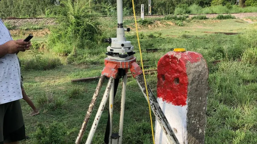
BTPL first established a GNSS control network running the length of the corridor, tied to the national datum and connected to available railway benchmarks so that levels and coordinates were consistent with the railway's own reference system. Pre-marked ground control and independent check points were laid along the corridor and observed by DGPS and RTK before UAV capture. The corridor was then flown in sequential photogrammetric blocks with planned overlap, with flight sequencing set around clearances, safety requirements near the running line and the workable weather window. Detail that the aerial data could not resolve reliably — track features, yard detail, structure dimensions, crossing geometry and obscured ground — was picked up by total station and RTK ground survey and integrated with the photogrammetric model into a single chainage-referenced corridor dataset.
How was the data processed?
The imagery was processed through aerial triangulation controlled by the surveyed ground control, followed by dense image matching to produce the corridor point cloud, which was classified to isolate the ground surface from vegetation, track structures and buildings. The DTM and orthophoto mosaic generated from this were used to extract the longitudinal section, cross-sections at the prescribed intervals and the planimetric detail into CAD, referenced throughout to route chainage. Ground-surveyed detail at yards, crossings and structures was merged into the same drawing set so that the corridor was represented as one coherent model.
How was accuracy verified?
Independent check points withheld from the adjustment were used to verify the terrain model along the corridor, supported by field-observed levels at benchmarks and at track-level reference points. Joins between adjacent photogrammetric blocks were compared in their overlap zones to confirm continuity of the merged corridor, and the integration of ground-surveyed yard and structure detail with the aerial model was checked for agreement. Extracted sections, chainage referencing and CAD layering were reviewed against the FLS deliverable requirements before submission.
What was delivered?
DIMTS was provided with a consistent, chainage-referenced base covering the full 310 km corridor, on which the doubling alignment, yard arrangements and structure proposals can be developed as part of the Final Location Survey. Holding the existing formation, adjoining ground and corridor features on one coordinated model allows the land requirement and constraint points along the route to be identified from a single verified dataset.
 DIMTS
DIMTS
Deliverable extracts (orthomosaic, terrain, CAD) will be added once cleared for publication (client-sensitive information removed per BTPL policy).
Planning a Similar Project?
Share your location, scope and required deliverables — BTPL will propose the appropriate survey methodology.